Design of Fish Passages & Ladders with HEC-RAS

Salmon and other migrating fish, such as shad, alewives and sturgeon, need access to freshwater habitat for spawning and rearing. In some cases, these fish need to swim thousands of miles through the oceans and rivers to reach their destination, but they are often blocked from completing their journey by man-made barriers, such as dams and roadway culverts. The design, creation and maintenance of fish passages (or fishways), including fish ladders, are key to the protection and restoration of fish populations and their natural habitat.
Hydraulic numerical modeling of fish passages is important in order to properly design the passageway for fish to successfully migrate. This article discusses how the US Army Corps of Engineers HEC-RAS water surface profile software can be used for the design and analysis of fish passages (including fish ladders), in addition to other aspects involved in the design and analysis of fish passages.
Fish Migration
A key component in the design of a fish passage are the migrating fish species physical characteristics and swimming capabilities. The biological basis needs to be considered in the engineering design criteria. Since migration timing and frequency of movement vary among species and watersheds, knowledge of the specific behavior of the target fish species is necessary for development of the fish passage criteria. Different species or age classes may migrate at different times of the year and therefore multiple hydrologic analyses may be needed to determine the controlling hydraulic requirements at any particular site. In addition, fish migration is both upstream and downstream, and the physical characteristics and capabilities of the migrating fish and the fish passage flow velocities and depths need to be considered.
For a given stream, juvenile and adult fish may be present during different times of the year and can have difficulty migrating down and upstream due to man-made obstructions. Both juvenile and adult fish have different swimming abilities and stream passage requirements. Hence, the design of the fish passages should take into account the physical characteristics and capabilities of the migrating fish—such as body type and size, swimming ability, impact resistance, and leaping ability.
Flow Velocity
Stream flow velocities in long uniform sections within a fish passage structure should be less than the sustained swimming capability for each species, and less than burst swimming ability over short distances (Katopodis 1991). Fish that are forced to swim through a structure with bursts or sustained cruising speeds will suffer stress from fatigue. If adult or juvenile migratory fish are unduly fatigued by a fish passage, their ability to survive and complete their life cycle may be significantly diminished. Resting alcoves should be provided if velocities within a fish passage structure exceed the swimming capabilities of the target species for long distances. Flow obstructions can be used to provide resting areas in the fish passage, providing velocity breaks and shadows to mimic natural stream conditions.
Flow Depth
Minimum low-flow stream depths within fish passages should be maintained to accommodate fish size, swimming abilities, and behavioral responses. For example, Washington Department of Fish & Wildlife recommends a maximum head differential of 12 inches for most adult salmonids, 6 inches for juvenile salmonids, and 3 inches for grayling. These depths are difficult to attain for many small headwater stream culvert crossings during normal flow conditions, so culvert size, shape, composition, and installation techniques become important design factors that regulate fish passage.
Jump Height and Pool Length
The jumping heights of target fish species must be identified when designing a fish passage structure using stepped pools or weirs. These typically include a maximum vertical height, and the jump pool length and depth needed to allow the fish to generate enough speed to clear the barrier. In addition, pool spacing and configuration must satisfy resting requirements of all target species.
Fish Passage Site Assessment
The engineering assessment of the fish passage site should include topographic and hydrographic surveys of the passage barrier and stream channel upstream and downstream of the barrier. Whenever possible, collect historic photos of the site, and interview nearby residents for their perspective on the area. Accurate contour maps and infrastructure (e.g., dams, diversions) as-builts plan sets are essential for developing an accurate site assessment. Fish habitat characterization should also be performed by an experienced fish biologist to evaluate migration patterns, holding pool areas, and environmental conditions that will affect fish migration and use of the fish passage feature.
Fish Passage Entrance Design
The fish passage entrance is designed to attract upstream migrant fish to the fish passage facility as they encounter a barrier or dam. The fish passage entrance is likely the most critical aspect to the facility design. Many fish passage structures use high velocity attraction flow at or near their entrances. This practice is based on behaviors observed in salmonids. Migratory salmon and steelhead tend to assume upstream migration paths by “cueing-in” on higher velocity currents. A fish passage entrance can be designed as a constriction to increase velocities compared to surrounding flow conditions, guiding fish into the structure based on their natural behaviors in finding upstream migration paths.
At active dam hydropower projects, operational characteristics, existing tailwater channel morphology, barrier effects on flow, areas of high water velocity and turbulence, and calm water areas may influence the optimal location of the entrance. For example, water washing over a dam spillway can confuse migrating fish heading upstream if the fish passage entrance is not located close by. Dam flood gates near the fish passage entrance should be opened in the spring to provide attraction water near the fish passage entrance.
The fish passage entrance is generally located at the most upstream point of fish migration, typically at the base of a dam, or where flow patterns cause fish to collect. The optimal entrance location varies with flow conditions, and sometimes multiple entrances are required to account for different conditions. Low flow entrances generally are oriented 45 to 90 degrees to the tailwater flow, and high flow entrances generally are oriented from 45 degrees to parallel with the flow. Site specific conditions such as spillway location and overflow depths may require variations from those criteria.
Depth and width at the fish passage entrance depends on size and flow conditions of the river or stream, attraction flow requirements, barrier dimensions, and biology of the target species. As an example, a minimum entrance width of 4 feet and depth of 6 feet is often used for upstream passage for American shad (Quinn 1994).
Fish Passage Transport Channel Design
A transport channel conveys water flow between components of an upstream fish passage, and is designed to provide attractive conditions for fish migration while minimizing stress or delay. Dimensions, velocity ranges, and lighting conditions are the principal design considerations for transport channels. In particular, the ability to provide ambient natural lighting without sharp light intensity transitions has been found to be an important aspect for avoiding stress or delay (Larinier and Travade 2002). In some cases, artificial lighting systems have been used in fish passages to avoid harmful light transitions and to promote movements by fish.
Fish Passage Exit Design
The fish passage exit is designed to allow for timely and safe movement of fish to open water above the passage barrier and to allow them to continue their upstream migration. The fish passage exit design typically includes gates or stop log slots to allow for closure of the fish passage for cleaning and maintenance, and trash racks to prevent debris from entering the fish passage without interfering with upstream fish movements. Pool and weir designs for larger rivers may require flow control gates, auxiliary water valves, and diffusers for maintenance of stable hydraulic conditions in the fish passage pools when headwater elevation fluctuations occur. Exit design details vary with differing fish passage types.
The location of the fish passage exit should include consideration of upstream channel configuration, flow patterns, proximity of shorelines, and location of hydropower turbine intakes. As fish exit the fish passage to the headpond above the barrier, delays in upstream migration may occur due to confusing flow patterns. Fish fallback may result from hydropower forebay flow patterns with circular currents or eddies that lead them near turbine penstocks or spillways. Study of headpond flow patterns can inform the decision process for locating the fishway exit to make it easier for fish to orient to stable flow vectors leading upstream. When feasible, the fish passage exit should be located along a shoreline and in an area as far as possible upstream from spillways or powerhouse penstocks to reduce risk of fish fallback.
Fishway and Ladder Design
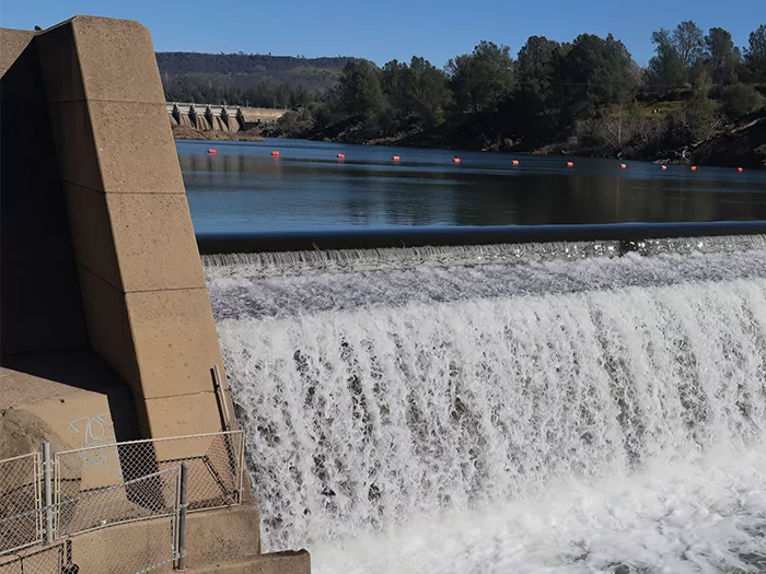
Fishways and ladders provide migrating fish with upstream passage around or through fish passage barriers. The general function of a fish passage facility is to attract fish into the structure and step them up the gradient created by the barrier to a point upstream, where they exit the ladder into the river and resume migration.
Fishways and ladders are constructed in many different configurations from a range of materials. Common variations include:
- excavated, earthen channels artificially roughened with large rocks
- semi-natural channels equipped with stair-stepped resting pools held in place with rocks, logs, or stoplogs
- concrete and/or metal structures that slow water velocity enough to provide upstream passage
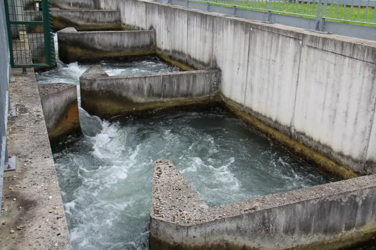
These structures are designed to function across a range of flows and are often built at fish passage barriers with excessive drops or velocities. Many fishways and ladders in common use today are pool-forming structures.
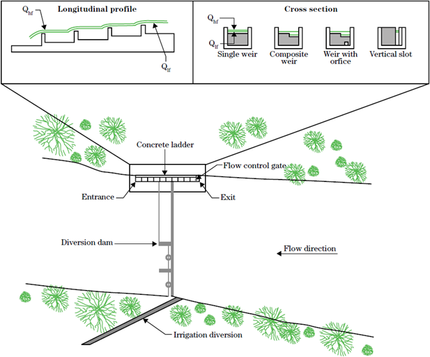
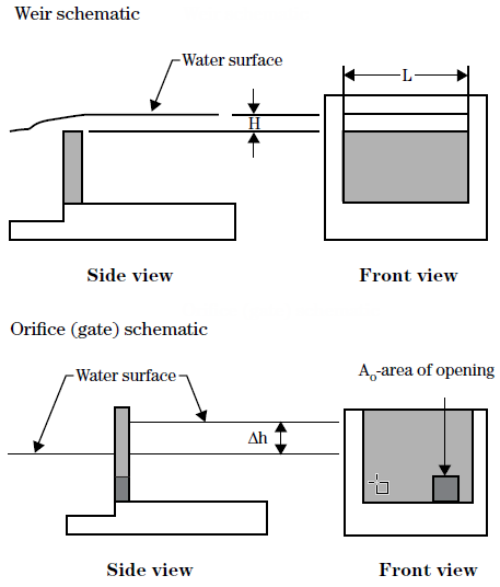
Fish ladders are commonly used to create pool-forming fishways using weirs and orifices. The resting pool depth in these structures is set by the height of channel-spanning weirs or headwalls. Water flows over the top of a weir (pool and weir), or through a submerged orifice (pool and orifice), depending upon the flow rate.
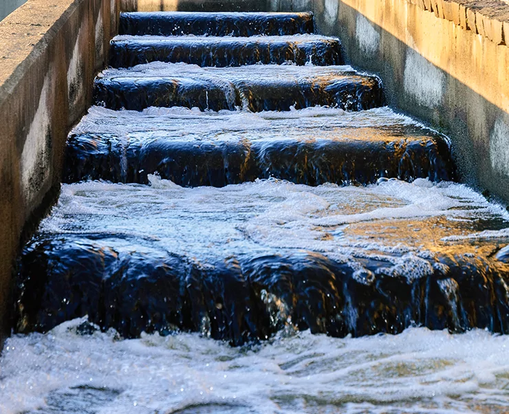
Fish ladder structures are designed for fish that are able to jump over obstacles (pool and weir), or for non-leaping fish, through submerged orifices at low flows. Water generally flows directly from pool to pool (rather than in a zigzag direction) to minimize energy expenditures on migrating fish. Fish ladders can take many forms, but are generally useful at gradients up to 10 percent.
For juvenile and small-bodied adult fish, pools should be spaced no further than 15 feet with a drop of no more than 9 inches across pools. Pool spacing can be increased to 20 feet and head differential to 12 inches for adult fish.
Another type of fish ladder that is sometimes used is a vertical slot. These structures are usually a concrete or metal rectangular channel in which a series of regularly spaced metal or concrete panels are installed perpendicular to the flow. Each panel has a narrow slot from top to bottom and is designed to work with low velocities. Water spills from chamber to chamber through vertical slots, and pools are formed as the flowing water is backed up at each slot opening. Pool depth and velocity in each chamber are determined by slot width and the quantity of water flowing down the fishway. Although vertical slot fishways can be designed to pass a wide variety of fish species over a significant flow range, they are less passable for fish that tend to follow or cling to walls or jump over weirs. The pools of a vertical slot fishway are hydraulically complex and do not supply resting areas as tranquil as a pool and weir/orifice ladder. Consequently, these structures must be set at a low gradient to pass weak-swimming fish, although they will pass strong swimming fish at relative steep slopes. The vertical slot fish ladder transports bed material efficiently, but is susceptible to debris blockages at each of the vertical slots.
Hydrologic Analysis Overview
The first step in the engineering design is the hydrologic analysis. Typically, designs require defining the range of high and low discharges the fish passage facility will operate within. Fish migration upstream may be limited during peak flow events, although migration patterns vary across species. Many fish migrate during spring or winter runoff events. Therefore, it is important to understand both the flood and baseflow characteristics if migration for the species of interest occurs during these periods.
Hydrologic Analysis for Gaged Streams
Hydrologic analysis techniques for characterizing flow during a specific period of interest or season usually involves flow-duration analysis of stream gage data. Developing a flood frequency curve provides the engineer with an estimate of flood magnitude and recurrence intervals for use in determining the size, configuration, and orientation of a fish passage facility. Computing flow duration is essential in determining the performance of a passage or screening structure across its operational range of flows. Flow-duration analysis is often performed by using the daily average flow (or other periods such as 3-day, 5-day, or weekly) during the period of interest.
Hydrologic Analysis for Ungaged Streams
Often, stream gages are not sufficiently close to a project site or located within the same river system. Several methods are available to the engineer for determining the magnitude and recurrence interval of seasonal high flows in ungaged watersheds. These include:
- regional regression equations,
- discharge correlation to adjacent gaged streams, or
- hydrologic rainfall-runoff modeling.
The U.S. Geological Survey (USGS) has developed regional regression equations for estimating flood events based on watershed area, annual precipitation, and regional variables. The USGS StreamStats Web-based GIS software incorporates these regression equations into an easy-to-use interface that provides streamflow statistics, drainage-basin characteristics, and other information for selected locations along streams. However, this software is not available for use for all states. For many other states, regression equations have been developed and can be obtained from state USGS offices.
The engineer can also use transfer techniques to estimate flow characteristics at a project location in an ungaged stream, using the results of an analysis of streamflow data at an adjacent, gaged location.
In addition, a variety of computer hydrologic modeling software (i.e., HEC–HMS, TR–20, TR-55, SWMM, etc.) are available to aid the engineer. Depending on the hydrologic model, either single event peak flow or continuous multiple event modeling can be performed.
Hydraulic Analysis Overview
Hydraulic analyses are performed to evaluate flow conditions through a fish passage. Typically, hydraulic design is an iterative process that balances available water and flow rates with site conditions and limitations, biological design criteria, and evaluation of various potential hydraulic flow control structures.
The first step in a hydraulic analysis is to characterize the streamflow and morphology. Important data elements to characterize the project site include:
- flow patterns,
- velocity and depth,
- fish migration paths and holding pool locations,
- identification of potential sediment scour and deposition zones, and
- forebay and tailwater conditions.
This information is essential in aiding the engineer in selecting the appropriate location and design configuration of the fish passage facility. Field measurements and surveys are needed, particularly to determine low-flow characteristics, site geometry, and local topography.
Once stream conditions are characterized, potential fish passage design alternatives can be developed and evaluated. Fish entrances, ladders, and exits typically use flow control structures such as weirs, gates, and orifices. The most important hydraulic information required in the design of a fish passage facility are:
- flow circulation patterns above, below, and adjacent to the fish passage site, and
- water surface elevations across the range of operating flows identified in the hydrologic analysis.
Hydraulic Analysis with HEC-RAS
To evaluate the stream hydraulics, a HEC-RAS computer hydraulic model is developed. This hydraulic model can then predict the water surface elevations, forebay and tailwater conditions, flow and diversion characteristics, and flow velocities and depths. Hydraulic analysis and design with HEC-RAS is an iterative process, balancing the various criteria and design requirements of the project. Therefore, the engineer should perform separate calculations of composite flow profiles due to the complex nature of the hydraulic structures associated with fish passage facilities.
Evaluating existing hydraulic conditions with HEC-RAS will provide the engineer with the forebay and tailwater rating curves for different flow rates used in setting the preliminary invert elevations for the fish passage entrance and exit areas. These rating curves are required for a wide range of flows for performing the fish passage design. The difference between upstream and downstream water surface elevations at the entrance and exit is the total change in head that the fish passage must be designed for. Structural head is a major determinant in how much flow will likely be diverted into the fish passage. Completing the streamflow hydraulics analyses for the range of operational flows allows the design of the fish passage facility to begin.
HEC-RAS Fish Ladder Model Simplification
Rather than modeling the entire fish ladder with HEC-RAS, a portion of ladder can modeled to represent the flow hydraulics of the ladder. This allows the engineer to easily adjust the pool height and length to provide the best flow characteristics for migrating fish. Generally 2 to 3 fishway pools are required to adequately analyze the fish ladder hydraulics.
Example HEC-RAS Fish Ladder Model
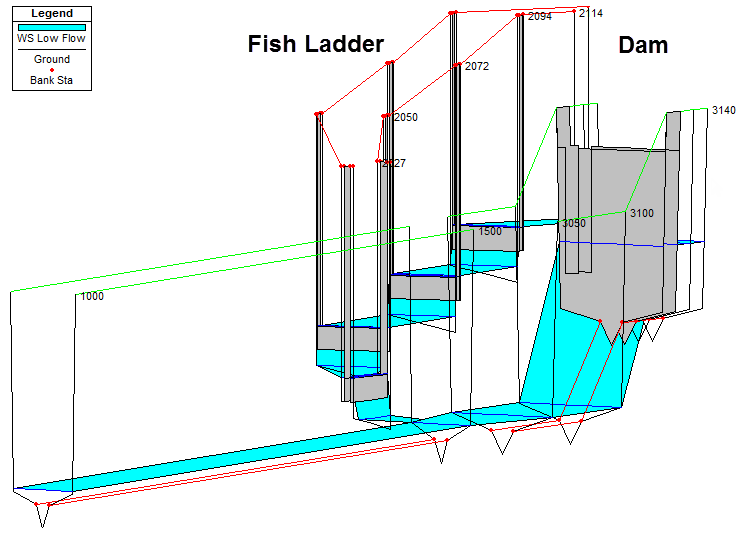
An example HEC-RAS steady and unsteady flow fish ladder model is provided below for review. In developing this model, the steps of the fish ladder are represented as individual inline structures.
For steady flow, the model is run with flow optimization defined at the headpond. HEC-RAS will then iterate the diversion of flow between the dam spillway and the fish ladder until they both have an equivalent water surface elevation at the upstream headpond. (Generally, the energy gradeline elevation is used in split flow optimizations. However, since there is no flow velocity in the pond, HEC-RAS will use the water surface elevation at storage nodes.)
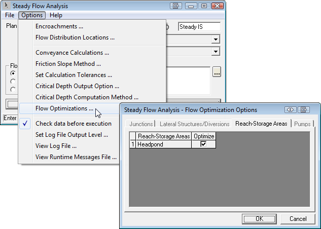
For steady flow conditions, a series of different flow events are run through the model to test the fish ladder design. An initial guess at the flow diverted through the fish ladder structure was made, and then iterated until balanced using the HEC-RAS flow optimization.
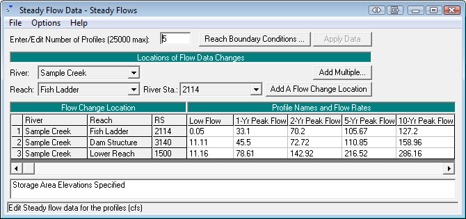
Initially, the actual flow that is diverted through the fish ladder is unknown. Running the steady flow HEC-RAS model with flow optimization defined at the headpond storage node, as shown below, allows the HEC-RAS software to determine the distribution of flow through the dam spillway and fish ladder. The final (optimized) flows were then re-entered into the Steady Flows dialog box, as shown above.
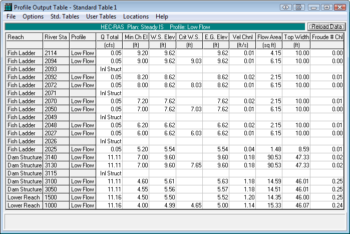
The results of the optimized flows at the headpond for the low flow event are shown below.
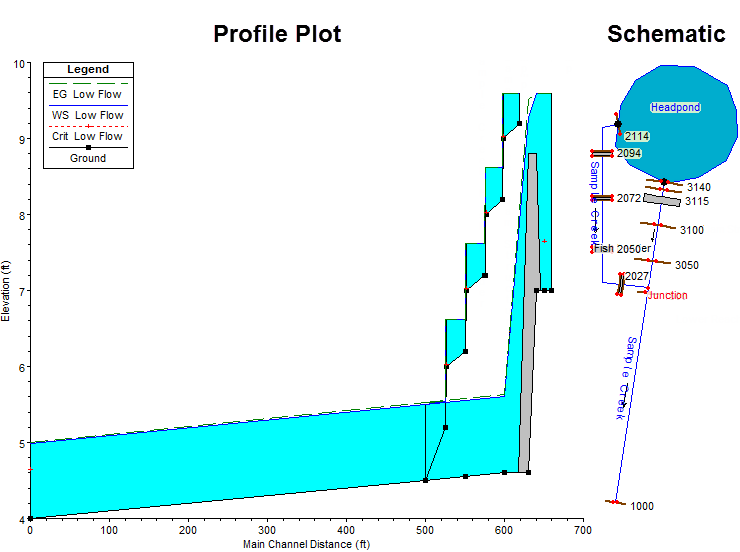
A profile plot and a schematic plot of the example HEC-RAS fish ladder model is shown below.
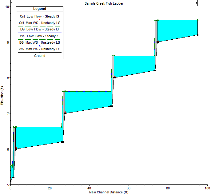
For the same HEC-RAS project, an unsteady flow boundary condition was defined using the low flow event. An unsteady flow model does not require flow optimization. The stream network is solved with a simultaneous solution method using the 1-D Saint Venant shallow water equations, and the HEC-RAS unsteady flow computational engine will determine the amount of flow that is diverted through the fish ladder.
A comparison of the steady flow and unsteady model results is shown below for the low flow event. The two water surface profiles are nearly identical.
The completed HEC-RAS example model can be downloaded by clicking on the below button.
Also Read: Fish Ladders vs. Flying Fish, Which Works Better?