
Welcome to CivilGEO Knowledge Base
Welcome to CivilGEO Knowledge Base
Minor losses represent sources of energy depletion along a river reach that are not related to friction loss. For example, minor losses are energy losses related to expansions and contractions along a reach, secondary currents, spiral currents, and eddies. They are generally created by increased turbulence and resistance to flow at areas in the reach where the direction of flow is changed or where other obstructions are present.

The most commonly encountered minor losses are:
Minor losses account for a significant percentage of the total energy loss in a reach. They must be entered into the total energy loss calculations to prevent discrepancies between actual conditions and HEC-RAS computed results.
Follow the steps below to define HEC-RAS minor loss coefficients:
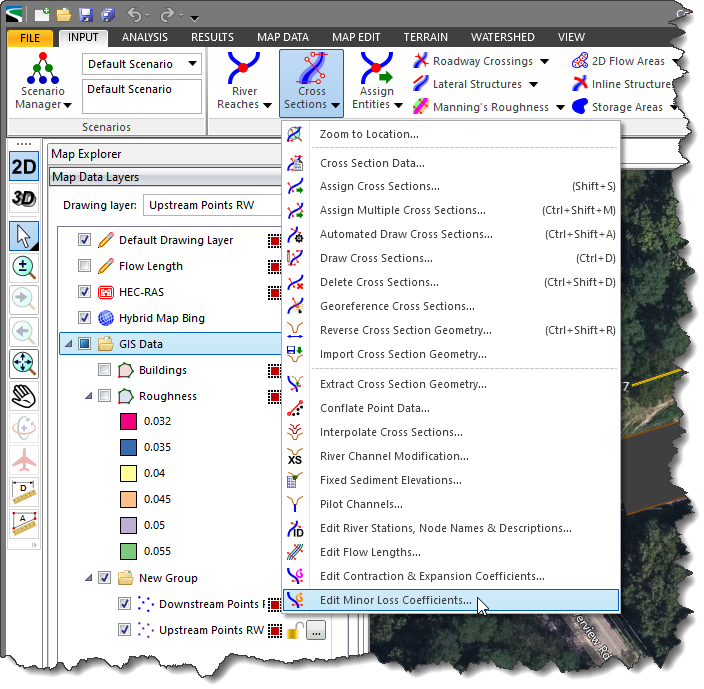
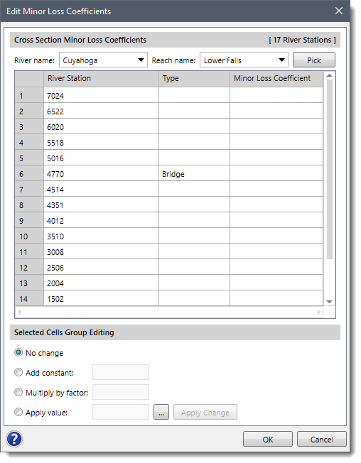
The following sections describe the Edit Minor Loss Coefficients command and how to interact with the above dialog box.
This section allows the user to select the desired river reach. Click the [Pick] button adjacent to the Reach name entry. The dialog box will temporarily disappear, and a prompt is displayed on the status line, informing the user what to do next. Select the river by clicking on it in the Map View.
Alternatively, the user can click the dropdown combo boxes adjacent to the River name and the Reach name entries and select the desired river reach.
This section displays a table listing the cross sections contained in the river reach and their respective minor loss coefficients. If an entry is blank, then no minor loss is applied to the cross section hydraulic computations. The user can export the table as a PDF file or a Microsoft Excel file, or copy the table to the clipboard.
This section enables the user to select the desired cells from the data table and then edit the minor loss coefficients either individually or in a batch. The user can edit the coefficients using:
To edit the cells coefficient, select the cells by clicking on them while pressing the [Ctrl] or [Shift] key; choose the desired cell-editing option; enter the change coefficient, and then click the [Apply Change] button.
Minor losses due to secondary and spiral currents are known as minor loss due to a meander bend and must be integrated into the model calculations. These losses can be accounted for in both steady flow and unsteady flow analysis. The minor loss coefficients can vary between 0.0 and 1.0. This loss coefficient gets multiplied by the velocity head at the cross section it corresponds to for calculating the minor energy loss. For steady flow computations, this energy loss gets added to the energy equation. For unsteady flow computations, the energy loss is converted to an equivalent force and then inserted into the momentum equation. In both cases, the energy loss is assumed to act as a force in the upstream direction slowing the flow down.
Since the average minor loss due to the meander bends through a meander bend is significant in the physical model, it is evident that spiral and secondary currents must be included in total energy loss calculations.
Minor losses due to a meander bend are calculated by first calculating the average velocity, total energy, and friction loss at each cross section in the model. After these values are calculated at each cross section, total energy loss through each meander bend is calculated.
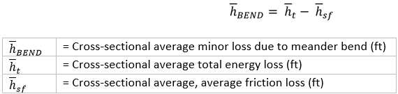
Once the average total energy loss between adjacent cross sections, the cross sectional average, and average friction losses are calculated, then the cross-sectional average minor loss due to meander bends (hBEND) is calculated by using the following equation:
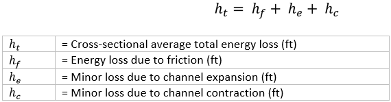
Note that the total energy loss ht in a reach is the sum of all the head losses along the flow path. It is calculated using the following equation:
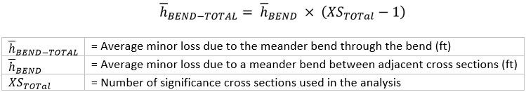
The cross sectional average minor loss due to meander bend calculated using Equation 1 is the final variable required to determine average minor loss due to meander bends. To calculate Average minor loss due to meander bends through a meander bend (hBEND-TOTAL) use the following equation:
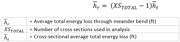
Finally, the average total energy loss through the bend (hr) is calculated. It is important to determine how significant average minor loss due to a meander bend through each meander bend is to the average total loss through the bend computation. The average total energy loss through the bend (hr) is calculated using the following equation:


CivilGEO G2 Reviews
4.8/5.0 Rating, Over 230 Reviews

GeoHECRAS is recognized as the top Civil Engineering Design Software with an average of 4.8 out of 5.0 rating from over 230 real user reviews on G2.


We use cookies to give you the best online experience. By agreeing you accept the use of cookies in accordance with our cookie policy.
When you visit any web site, it may store or retrieve information on your browser, mostly in the form of cookies. Control your personal Cookie Services here.


