
Welcome to CivilGEO Knowledge Base
Welcome to CivilGEO Knowledge Base
This article discusses the requirements for HEC‑RAS cross section placement, spacing, layout, geometry, and other data.
Boundary geometry for the HEC‑RAS analysis of flow in natural streams is specified in terms of ground surface cross sections and the measured flow distances between them (reach lengths). Cross sections are located at intervals along a stream to characterize the flow carrying capability of the stream and the adjacent floodplain. The cross sections should extend across the entire floodplain and should be perpendicular to the anticipated flow lines. Occasionally it is necessary to layout cross sections in a curved or dog‑leg alignment to meet this requirement. Every effort should be made to obtain cross sections that accurately represent the stream and floodplain geometry.
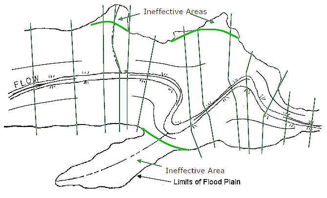
An example cross section layout is shown in the below figure. The general approach to laying out cross sections is to ensure that the cross sections are perpendicular to the flow lines. This requires an estimation of what the flow lines will look like in the overbank areas away from the main channel. One option is to draw a stream center line down the main channel along what is perceived to be the center of mass of flow. The same thing should be done for the left and right overbanks. The assumed flow paths for the channel and overbank areas are shown as dashed lines in below figure. These lines will not only help in drawing the cross sections perpendicular to the flow lines, but they also represent the centroid flow path for measuring the reach lengths between the cross sections.
Cross sections are required at representative locations throughout a stream reach and at locations where changes occur in discharge, slope, shape, or roughness, at locations where levees begin or end and at bridges or inline control structures such as weirs. Where abrupt changes occur, several cross sections should be used to describe the change regardless of the distance between cross sections.
Cross section spacing is also a function of stream size, slope, and the uniformity of cross section shape. In general, large uniform rivers of flat slope normally require the fewest number of cross sections per mile. The purpose of the study also affects spacing of cross sections. For instance, navigation studies on large relatively flat streams may require closely spaced (e.g., 200 feet) cross sections to analyze the effect of local conditions on low flow depths, whereas cross sections for sedimentation studies, to determine deposition in reservoirs, may be spaced at intervals on the order of miles.
The choice of friction loss equation may also influence the spacing of cross sections. For instance, cross section spacing may be maximized when calculating an M1 profile (backwater profile) with the average friction slope equation or when the harmonic mean friction slope equation is used to compute M2 profiles (drawdown profile). The HEC‑RAS software provides the option to let the program select the friction slope equation.
Each cross section in a HEC‑RAS model is identified by a river, reach, and river station. The cross section geometry is described by entering the station and elevation (X‑Y data) from left to right, with respect to looking in the downstream direction. The river station may correspond to stationing along the channel, mile points, or any fictitious numbering system. The numbering system must be consistent in that HEC‑RAS assumes that higher river stations are upstream and lower river stations are downstream.
Each data point in the cross section geometry is given a station number corresponding to the horizontal distance from a starting point on the left. Up to 500 data points may be used to describe the cross section geometry. Cross section data are traditionally defined looking in the downstream direction. The program considers the left side of the stream to have the lowest station numbers and the right side to have the highest. Cross section data are allowed to have negative stationing values. Stationing must be entered from left to right in increasing order. However, more than one point can have the same stationing value, as in the case of a vertical wall. The left and right stations separating the main channel from the overbank areas must be specified for the cross section. End points of a cross section that are too low (below the computed water surface elevation) will automatically be extended vertically and a computational note indicating that the cross section has been extended will show up in the output for that cross section. The program adds additional wetted perimeter for any water that comes into contact with the extended vertical walls.
Other data are required for each cross section:
Numerous program options are available to allow the user to easily add or modify cross section data. For example, when the user wishes to repeat a surveyed cross section, an option is available from the interface to make a copy of any cross section. Once a cross section is copied, other options are available to allow the user to modify the horizontal and vertical dimensions of the repeated cross section data.


CivilGEO G2 Reviews
4.8/5.0 Rating, Over 230 Reviews

GeoHECRAS is recognized as the top Civil Engineering Design Software with an average of 4.8 out of 5.0 rating from over 230 real user reviews on G2.


We use cookies to give you the best online experience. By agreeing you accept the use of cookies in accordance with our cookie policy.
When you visit any web site, it may store or retrieve information on your browser, mostly in the form of cookies. Control your personal Cookie Services here.


